Results 0 items
Enter your search criteria
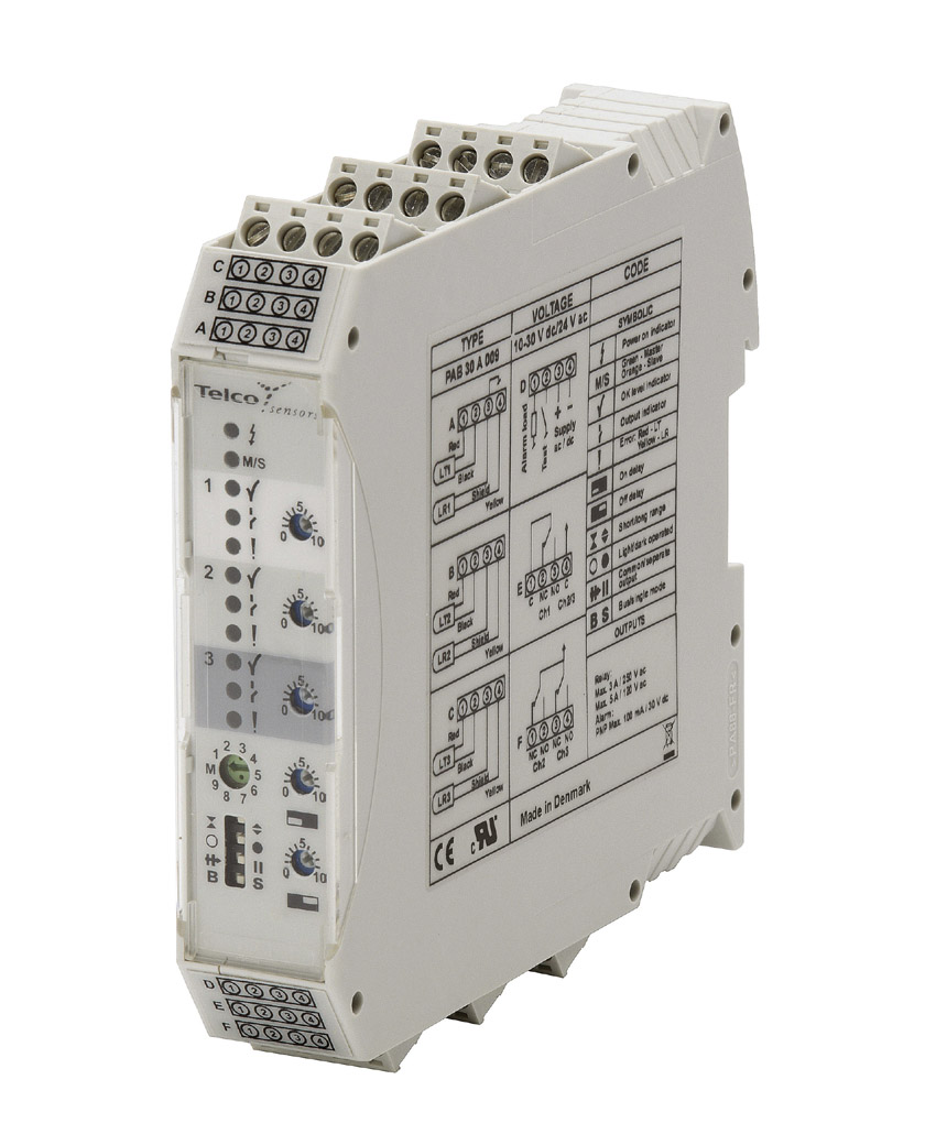
Photoelectric Amplifier Bus Automatic SERIES
Photoelectric Amplifier Bus Auto
![]()


The PABA 30 is a 3-channel photoelectric amplifier, which is to be used in conjunction with 3 sets of remote transmitters LT and receivers LR from the series 100, 110 and 120. The 3 channels operate independently of each other with their own set of remote transmitter and receiver. The multiplexing function ensures that optical cross talk between channels is prevented.
This amplifier series offers versatile automatic gain adjustment with potentiometer adjustable excess gain (for each individual channel) and switch selectable long or short range which ensures that the transmitting power level is adjusted according to the application, thus achieving optimal hysteresis and excess gain. Once set up, the amplifier will automatically and continuously compensate for moderate contamination and misalignment during operation in accordance with the selected auto gain settings. The series offers a choice between 3 individual relay or 3 individual transistor outputs, with an adjustable 0-10 sec on/off time delay. Light or dark function is switch selectable.
The amplifiers from the PABA 30 A series can be connected together with up to 9 amplifiers from the PAB(A) series via a bus rail connector positioned on the DIN rail, to form a modular master/slave system with up to a total of 30 channels. The bus connection enables communication between the amplifiers, which allows the channels of all the amplifiers to be multiplexed, ensuring that optical cross talk between channels is prevented and allows a common output from the amplifier modules. Both the PABA 30 A and PABA 30 S can share power supply via the bus connection (except 90-240 V ac types).
The amplifier offers a test input, which is used for either disabling or enabling the transmitting power temporarily for test purposes. The system includes an alarm output, which is used to indicate if the transmission power is at maximum and the selected excess gain level is not obtained or if a sensor is faulty/disconnected. The sensor LED drive powers the optional monitor LEDs available on the remote sensors – output (LT) and power (LR).
All products include a 3-year worldwide warranty.
| Function | Amplifier |
| Supply Voltage | 10 – 30 V dc / 24 V ac |
| Number of Channels | 3 |
| Sensing Range | 39 m |
| Sensitivity Adjustment | Automatic gain adjustment with adjustable excess gain |
| Output | 3 individual relays |
| Timer | On/Off Delay |
| Housing | Removable screw terminals |
| Supply Voltage | 10 - 30 V dc or 24 V ac |
| Voltage Tolerance | +/- 10 % |
| Current Consumption | Max. 2,6 W |
| Response Time ton / toff, Relay | Short range: 39 ms / 32 ms Long range: 75 ms / 68 ms |
| Output, Relay | 250 V ac / 3 A, 120 V ac / 5 A |
| Alarm Output, Transistor | PNP - 30 V dc / 100 mA |
| Test Input | Yes |
| Power On Indicator | Green LED |
| Output Indicator | Yellow LED |
| Alarm Indicator | Red / yellow LED |
| LR Sensor Failure Indicator | Yelow LED |
| LT Sensor Failure Indicator | Red LED |
| Master/Slave Address Indicator | Green / orange LED |
| Signal Level Indicator | Green LED |
| Sensor Monitor LED Drive | Green LED on the receiver: ‘Power ON’ Yellow LED on the transmitter: PABA output activated |
| Hysteresis | Approx. 35 % |
| Operation Frequency, Relay | Short range: 14 Hz Long range: 7 Hz |
| Delay Time ton / toff | 0 – 10 sec, adjustable |
| Housing Material | Polyamide |
| Operation Temperature | – 10 to +50 °C |
| Storage Temperature | – 40 to +80 °C |
| Sealing Class | IP 40 |
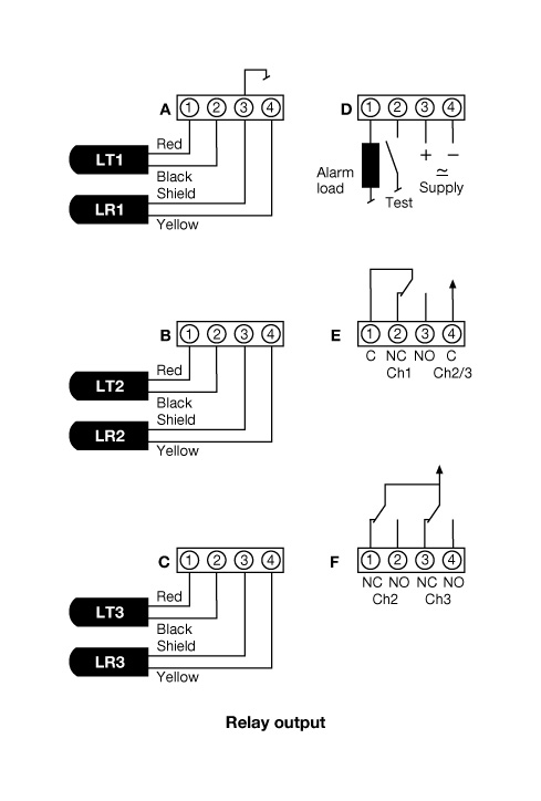 Wiring Diagram
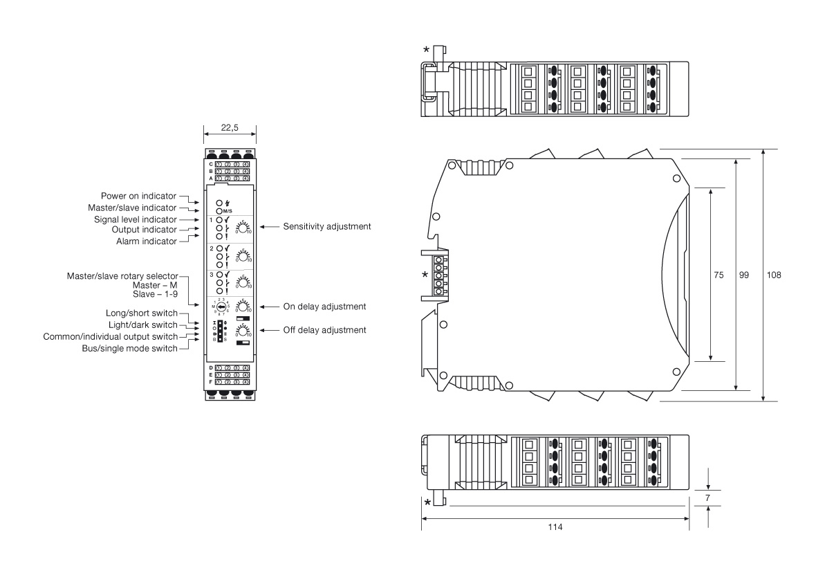 Dimensions
Enter your search criteria
Or
Find the Telco product type you're looking for with the help of criteria search filters in the Telco product finder